Integrated Sink Drain Alignment Before Hotel Vanity Production
Integrated Sink Drain Alignment before Repeated Vanity Production
The vanity looks finished until the plumber raises the trap into place. The outlet sits 35 mm forward of the cabinet opening, the upper drawer crosses the fitting body, and the overflow tube has no gentle route to the drain assembly. None of those conflicts appears in the front elevation.

That is why I treat integrated sink drain alignment as a section drawing and mock-up problem. The basin shape fixes the outlet. The cabinet fixes the rail and drawer envelope. The wall fixes the rough-in. If those three drawings are developed separately, the installer becomes the person asked to redesign the package in a finished bathroom.
Here's what I'd do: build one working unit with the specified drain, overflow, trap, drawer, and rear access. Run water. Open everything. Remove the trap without dismantling the cabinet. Then release quantity production.
Table of Contents
- What the section drawing must show
- How overflow and drainage paths work together
- Where cabinets and drawers create conflicts
- How to test the working mock-up
- Questions before production
Draw Integrated Sink Drain Alignment in Section
An integrated basin combines the counter and bowl into one fabricated component. The general function of a sink is simple enough, but a repeated vanity package needs exact geometry. I want a section through the bowl center and another through the overflow connection when the two do not share the same plane.
Start at the finished top surface
The drawing should show counter height, bowl rim condition, internal slope, bowl depth, rear ledge, faucet position, and outlet center. A shallow bowl may preserve drawer space but increase splash. A deep bowl may feel generous while pushing the fitting into the top drawer envelope.
For integrated sink drain alignment, the drawing also needs finished overhangs and wall scribes. A cabinet may be centered between rough walls while the top shifts to absorb a side tolerance. If the drain is dimensioned from the cabinet center but fabricated from the top center, both components can be correct and still miss each other.
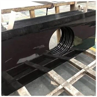
An integrated quartzite sink also needs fabrication-aware support around the bowl and drain area. Natural material, joints, reinforcement, repair positions, and handling requirements must remain visible in the approval record. The surface cannot be treated as an ordinary flat top after the bowl is formed.
A white crystal quartz integrated sink may use a different manufacturing route, yet the drain section still needs the actual bowl depth, outlet body, overflow connection, cabinet opening, and service movement. Material consistency does not remove component coordination.
Follow the fitting below the bowl
The drain drawing needs the actual fitting stack, not a symbol. Show flange or waste body depth, seals, overflow entry, tailpiece, trap, connection direction, and removal movement. A component may fit when assembled in open air but remain impossible to tighten inside a narrow cabinet.
I reserve hand space around threaded connections. Housekeeping does not need access there every day, but maintenance eventually will. A leak behind a drawer is a pain in the neck because the first sign may be a swollen panel rather than water on the floor.
| Coordination point | Drawing input | Physical check | Hold condition |
|---|---|---|---|
| Bowl outlet | Center from finished front and side | Measure actual fabricated center | Outside cabinet opening or fitting envelope |
| Overflow | Opening, channel, tube, connection | Fill basin to overflow level | Leak, backfall, kink, inaccessible joint |
| Trap | Actual model and removal path | Install and remove inside cabinet | Rail, drawer, shelf, or back conflict |
| Drawer | Box, runner, notch, open travel | Cycle loaded drawer repeatedly | Contact with tube, valve, or trap |
| Wall rough-in | Center, height, valve spacing, tolerance | Mock wall or surveyed room condition | Connection needs forced offset or cabinet cutting |
The Overflow Is a Water Path, Not a Decorative Slot
Decide whether the basin has an overflow
Some basin designs include an overflow opening; others do not. The decision affects drain fitting compatibility, water capacity, cleaning, local requirements, and guest expectations. The responsible designer and plumbing team must establish what the project requires. I do not add an overflow by habit or delete it for a cleaner rendering.

The overflow detail belongs inside integrated sink drain alignment because its tube or channel usually joins the waste body below the bowl. That connection adds depth and often shifts the usable tool angle. A drawer notch that fits the trap alone may still hit the overflow elbow when everything is assembled.
If there is no overflow, the drain fitting and operational guidance must match that configuration. If there is one, the complete path has to be fabricated, connected, cleaned, and tested. A visible slot without a reliable route is worse than no slot because it creates false confidence.
Avoid flat pockets and tight bends
An overflow channel needs continuous fall toward its connection where the design allows it. Flexible tubing should not kink behind the bowl or rub against moving drawers. Concealed channels need a fabrication method that the supplier can inspect before closing the assembly.
I want photographs of hidden work before it becomes inaccessible. Those images belong with the mock-up record. Don't ask me how I know: the one joint nobody photographs is often the one maintenance cannot reach later.
Test with the real drain assembly
A temporary plug does not test the final connection. Fill the basin with the specified fitting installed. Observe the overflow path, drain speed, joint leakage, standing water, and underside moisture. Repeat after the assembly has been opened and reconnected once.
Protect Cabinet Space before the Plumber Arrives
The existing Bathroom Vanity Plumbing Rough-In article owns the wider wall-side coordinates. This page stays closer to the basin: outlet, overflow, fitting stack, trap envelope, and the cabinet parts immediately around them.
Rails must support without blocking service
The cabinet top rail or stretcher helps carry the surface, but it cannot pass through the drain fitting. Moving the rail may weaken support or interfere with hardware. The top and cabinet drawings need one shared section showing every rail, bracket, fixing, and access opening.
In a wall-hung cabinet, integrated sink drain alignment shares space with the hanging rail and wall fixings. I mark those fixing zones before anyone widens a plumbing opening. Removing material from the wrong rail to clear a trap can reduce cabinet support and make later adjustment harder.
The Bathroom Vanity Countertop Support article explains long spans, cutouts, rails, and brackets in more detail. For an integrated bowl, I use that support logic while reserving a clean plumbing corridor.
Drawers need an operating envelope
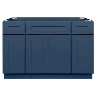
A U-shaped drawer can wrap around plumbing, but its notch must match the real fitting and rough-in tolerance. A shallow top drawer may work when the bowl and outlet stay high enough. A false front may simplify coordination but reduce storage. These are room-package decisions, not workshop improvisations.
I check the drawer fully loaded because runner movement and cabinet flex can reduce the apparent clearance. A tube that clears an empty drawer by 3 mm may knock during daily use. Small thing. Big annoyance.
Valves and traps must remain removable
Service access is not a photograph of an open cabinet. The maintenance person needs to reach shutoff valves, disconnect the trap, replace seals, and remove a drawer without damaging the top. I ask someone unfamiliar with the mock-up to perform those actions. That reveals whether the access is obvious or only possible because the designer knows the trick.
Run One Working Mock-Up through the Full Test
The active parent, Integrated Sink Vanity Top: Bowl Geometry, Drainage, Support, and Replacement, connects material, bowl form, cabinet support, cleaning, and future replacement. This narrower test begins after those choices are provisionally set and asks whether the water path works inside the real cabinet.
Before water
Measure the fabricated outlet against the approved drawing. Install the specified drain, overflow parts, trap, valves, and connectors. Confirm gasket seating and tool access. Open and close doors and drawers. Check that no hardware rubs a tube.
I photograph integrated sink drain alignment from the open front and from below before water starts. The images show fitting orientation, hose routing, rail clearance, valve access, and drawer position. Those views become the comparison record when another room needs diagnosis after installation.
During water
Run the faucet at normal flow and watch how the bowl clears. Check the rear ledge and corners for standing water. Close the drain, raise the level to the overflow where fitted, and inspect every concealed connection with dry tissue or another suitable leak-detection method.
After water
Empty the basin and look for residual water. Inspect the underside, cabinet base, rails, and drawer. Remove and reinstall the trap. Repeat the water test. The separate Bathroom Vanity Water Test before Hotel Handover article carries this process into final room inspection.
The Hard-Won Lesson: A centered drain can still miss the cabinet opening
The basin outlet is centered on the vanity top, and the cabinet opening is centered on the cabinet. The two still miss because the top overhang and wall scribe shift the cabinet center relative to the finished top. Once the waste fitting is added, its body catches the rail by less than 10 mm. Every drawing looks symmetrical on its own. The assembled section does not.
The Lesson: Dimension every drain center from the same finished reference, not from separate component centerlines.
Release the Assembly, Not Three Separate Components
Use one coordinate system
Choose finished wall, finished floor, and a defined vanity side as shared datums. Locate the bowl, outlet, faucet, rough-in, rails, drawer notches, and valves from those references. Record tolerances where site and manufactured parts meet.
A room-type schedule should carry the same integrated sink drain alignment references. Single vanities, double vanities, accessible rooms, and suites may use different bowl positions or cabinet interiors. Copying one coordinate across all room types can move a drain into a partition, drawer, or support that does not exist in the original mock-up.
Freeze named components
A drain body, trap, valve, or faucet change can invalidate the section. The room schedule should record approved models or dimensional envelopes and establish who can authorize substitutions. "Equivalent" is not enough when a fitting becomes 18 mm deeper inside a fixed drawer space.
Escalate before cutting the cabinet
If site plumbing misses the approved envelope, photograph the wall, rough-in, vanity label, and measured offsets. Do not cut rails or drawers while the cause is unclear. Compare the as-built measurements with the approved section and mock-up record, then involve the supplier, cabinet designer, plumber, and responsible project lead.
After an approved correction, update the record. Integrated sink drain alignment is not closed when one installer finds a workaround in one room. The revised detail must show what changed, which room types it affects, and whether factory production, site plumbing, drawer notches, or spare components need the same revision.
The handover team should receive the final section, approved component list, mock-up photographs, test result, and access instructions. I also include the room-type exceptions. That small package gives maintenance a clear reference when a trap, valve, or drawer needs service months later, without asking staff to reverse-engineer the hidden arrangement from a finished cabinet.
Label removable drawers and access panels by room type. Maintenance should know which part comes out first and which fasteners must not be disturbed before reaching the plumbing.
Record that access sequence clearly.
I keep the section with my mock-up record.
Quick-Reference Checklist for Integrated Basin Drainage
- Dimension the bowl outlet from finished wall, front, and side references.
- Draw the actual waste body, overflow path, trap, and removal movement.
- Overlay cabinet rails, drawers, shelves, valves, and service openings.
- Freeze fitting models or approved dimensional envelopes before production.
- Build one working cabinet-and-top mock-up with real plumbing components.
- Run, hold, overflow, drain, leak, drawer, and service-access tests.
Frequently Asked Questions
1. Where should an integrated basin drain be located?
The location must support bowl drainage and fit the approved cabinet and wall plumbing envelope. Centered, rear-offset, and side-offset outlets can all work when coordinated. Use the actual fitting stack and shared finished references rather than choosing a center point from appearance alone.
2. Does every integrated sink need an overflow?
No universal answer fits every project. Basin design, drain fitting, operational use, local requirements, and the responsible plumbing design all matter. If an overflow is specified, its complete path must remain cleanable, connected, accessible where needed, and tested with water.
3. How much clearance should remain around the trap?
Use the specified component dimensions, tool access, connection movement, and future removal path. A nominal gap is not enough if a drawer, rail, or valve blocks the hand and tool angles. Verify clearance physically on the working mock-up.
4. How is integrated sink drain alignment checked before mass production?
Measure the fabricated outlet, install the approved drain and overflow, connect the trap inside the real cabinet, operate every drawer, run and hold water, inspect for leaks, and remove the trap once. Record the approved section and mock-up photographs for production.
5. What should happen if the wall rough-in misses the drain?
Photograph and measure both centers from the same finished references. Stop cabinet cutting or forced connection work. Compare the as-built report with the approved drawing and mock-up, then agree on the responsible correction with the plumber, cabinet supplier, top fabricator, and project lead.
Final Conclusion
Integrated sink drain alignment succeeds when the bowl outlet, overflow, fitting stack, trap, wall rough-in, rails, drawers, and service path share one coordinate system. Draw the section with real components, test one working assembly, and freeze the result before repeated production. This is where you don't cheap out, because KA UNITED would rather move one line on a drawing than ask installers to cut fifty cabinets around the same missed drain.
References
- Bathroom Planning Guidelines, National Kitchen and Bath Association.
- International Plumbing Code, International Code Council.
- Uniform Plumbing Code, International Association of Plumbing and Mechanical Officials.
- ANSI A117.1 Accessible and Usable Buildings and Facilities, International Code Council.
- Dimension Stone Design Manual, Natural Stone Institute.
- Cabinet and Countertop Planning Guidance, National Kitchen and Bath Association.
- Manufacturer Installation Instructions for Approved Drain, Trap, Faucet, and Overflow Components.
- Search Essentials and Helpful Content Guidance, Google Search Central.